Documentation for:
- LX4 PRO
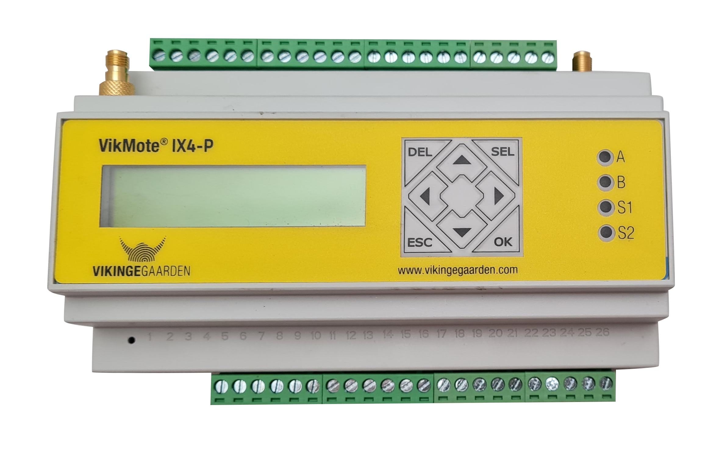
|
Documentation for:
|
|
LX4 PRO can be used as a replacement for DX4i PRO
A SIM card must be inserted in the unit if it is not factory-delivered with a SIM card installed:
| Supply voltage | Terminal | Use | Note |
| 8-36 VDC |
28 - SUPP 29 - SUPP |
Plus |
Minimum 12 V if 0-10 V outputs are used |
| 27 - PGND | Minus |
| Digital inputs | Terminal | Use | Note |
| Ground 1 | 40 - SGND | Ground for inputs 1..4 | Must always be connected |
| Input 1 | 41 - DI1 |
If jumper 1 is in position N, the signal on DI1 must be 8-40 VDC (PNP) If jumper 1 is in position S, the signal must be between SGND and DI1 (S0/NPN) |
|
| Input 2 | 42 - DI2 |
If jumper 2 is in position N, the signal on DI2 must be 8-40 VDC (PNP) If jumper 2 is in position S, the signal must be between SGND and DI2 (S0/NPN) |
|
| Input 3 | 43 - DI3 |
If jumper 3 is in position N, the signal on DI3 must be 8-40 VDC (PNP) If jumper 3 is in position S, the signal must be between SGND and DI3 (S0/NPN) |
|
| Input 4 | 44 - DI4 |
If jumper 4 is in position N, the signal on DI4 must be 8-40 VDC (PNP) If jumper 4 is in position S, the signal must be between SGND and DI4 (S0/NPN) |
|
| Input 5 | 45 - DI5 | The signal on DI5 must be 8-40 VDC (PNP) | Use only PNP signal |
| Input 6 | 46 - DI6 | The signal on DI6 must be 8-40 VDC (PNP) | |
| Input 7 | 47 - DI7 | The signal on DI7 must be 8-40 VDC (PNP) | |
| Input 8 | 48 - DI8 | The signal on DI8 must be 8-40 VDC (PNP) | |
| Ground 2 | 49 - SGND | Ground for inputs 5..8 | Must always be connected |
| Digital outputs | Terminal | Use | Note |
| Supply voltage 8-36 VDC | 30 - DOUT SUPP + | Supply voltage for outputs |
Terminal 30 can be connected to terminal 29 |
| 39 - DOUT GND - | |||
| Output 1 | 31 - DO1 | Contact set 1, NO |
Max. load is 1.5 A per output Max. inductance for switching is 20 mH per output |
| Output 2 | 32 - DO2 | Contact set 2, NO | |
| Output 3 | 33 - DO3 | Contact set 3, NO | |
| Output 4 | 34 - DO4 | Contact set 4, NO | |
| Output 5 | 35 - DO5 | Contact set 5, NO | |
| Output 6 | 36 - DO6 | Contact set 6, NO | |
| Output 7 | 37 - DO7 | Contact set 7, NO | |
| Output 8 | 38 - DO8 | Contact set 8, NO |
| Analogue inputs | Terminal | Use | Note |
| Input 1 | 22 - AI1 |
If jumper Ain1 is not installed, a 0-10 V signal is used on AI1 If jumper Ain1 is installed, a 4-20 mA signal is used on AI1 |
Connect the transmitter between AINx and AGND using 0-10 V or 4-20 mA |
| Input 2 | 23 - AI2 |
If jumper Ain2 is not installed, a 0-10 V signal is used on AI2 If jumper Ain2 is installed, a 4-20 mA signal is used on AI2 |
|
| Input 3 | 24 - AI3 |
If jumper Ain3 is not installed, a 0-10 V signal is used on AI3 If jumper Ain3 is installed, a 4-20 mA signal is used on AI3 |
|
| Input 4 | 25 - AI4 |
If jumper Ain4 is not installed, a 0-10 V signal is used on AI4 If jumper Ain4 is installed, a 4-20 mA signal is used on AI4 |
|
| Ground | 26 - AGND | Ground for analogue inputs | Must always be connected to the transmitter reference point (ground) |
| Analogue outputs | Terminal | Use | Note |
| Output 1 | 20 - AO1 |
If jumper Aout1 is in position V, a 0-10 V signal is used on AO1 If jumper Aout1 is in position C, a 4-20 mA signal is used on AO1 |
Connect the equipment between AONx and AGND using 0-10 V or 4-20 mA |
| Output 2 | 21 - AO2 |
If jumper Aout2 is in position V, a 0-10 V signal is used on AO2 If jumper Aout2 is in position C, a 4-20 mA signal is used on AO2 |
|
| Ground | 26 - AGND | Ground for analogue outputs | Must always be connected to the transmitter reference point (ground) |
| RS232 communication | Terminal | Use | Note |
| Port 1 | 14 - TXD |
Transmits data |
RS232 port with RTS/CTS handshaking signals |
| 15 - RXD |
Receives data |
||
| 16 - RTS | Request to send | ||
| 17 - CTS | Clear to send | ||
| Ground | 11 - SGND | Ground for RS232 |
| RS485 communication | Terminal | Use | Note |
| Port 1 |
9 - RSA 1 (+) |
RS485 non-inverting signal (A) |
Install jumper TERM1 to activate a 120 ohm resistor on the bus Read more about termination here |
| 10 - RSB 1 (-) |
RS485 inverting signal (B) |
||
| Ground | 8 - SGND | Ground for RS485 |
| RS485 communication | Terminal | Use | Note |
| Port 2 | 12 - RSA 1 (+) |
RS485 non-inverting signal (A) |
Install jumper TERM2 to activate a 120 ohm resistor on the bus Read more about termination here |
| 13 - RSB 1 (-) |
RS485 inverting signal (B) |
||
| Ground | 11 - SGND | Ground for RS485 |
| 1-Wire communication | Terminal | Use | Note |
| Port 1 | 6 - 1Wire | 1-Wire bus |
Connect the equipment between 1Wire and SGND |
| 7 - 1Wire-LED | 1-Wire ID button with LED lamp | ||
| Ground | 5 - SGND | Ground for 1-Wire |
| MBus communication | Terminal | Use | Note |
| Port 1 | 18 - M-BUS+ | MBus signal plus |
Connect the equipment between M-BUS+ and M-BUS- |
| 19 - M-BUS- | MBus signal minus / ground |