Shared Runtime Analog Input Settings
Use this page for analog source setup in the shared runtime layer. This includes signal type, scaling, filtering, alarm setpoints, alarm texts, and channel behaviour.
- The listed default values can be changed to match the installation.
- Set signal type and measurement range here before configuring product-specific behaviour, alarm delivery, or DataGuard reporting.
- Use the sections below in the same order as the controller processes the signal.
- Use DataGuard via Analog Inputs when the scaled value must be logged as history or exported to Emiko.
Typical Signal Logic
An analog input is first scaled to the required engineering range. After that, alarm setpoints, hysteresis, texts, and logging are applied to the finished value.
The example below illustrates a typical level setup.
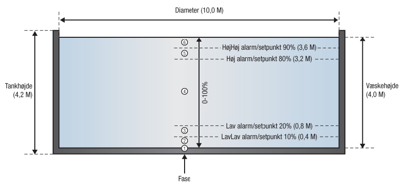
Figure: Typical analog input flow from scaling through alarms and data logging.
The example below illustrates how hysteresis prevents repeated alarms around the same threshold.
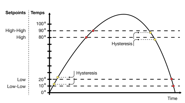
Figure: Hysteresis example that prevents repeated alarm changes around the same setpoint.
Transmitter Setup
Wire the transmitter before configuring signal type and scaling. See Analog Transmitter Wiring for 4-20 mA and 0-10 V wiring principles.
Signal Type
Select the electrical signal type that matches the connected transmitter output.
On LX5 ECO, flex channels configured as analog inputs are available as logical AI channels. Use VRTYPE 4 for direct flex 0..30 V input. Use VRTYPE 5 for flex 0..30 V normalized to logical 0..10 V, where 10 V is normal full scale and higher values are retained as overrange.
| Parameter | Index | Range | Format | Default | Example |
VRTYPE# |
1..32 | 0..5 |
0 = 4-20 mA 1 = 0-5 V 2 = 0-10 V 3 = 0-20 mA 4 = 0-30 V 5 = 0-30 V > 0-10 V |
0 | VRTYPE1 2 |
Measurement Range Minimum
Define the engineering value that corresponds to the low end of the input signal.
- Enter the real engineering value directly.
- For a
0..100 °Ctransmitter, set the minimum range value to0.
| Parameter | Index | Range | Format | Default | Example |
TMIN# |
1..32 | -32768..32767 | Engineering value | 0 | TMIN1 10 |
Measurement Range Maximum
Define the engineering value that corresponds to the high end of the input signal.
- Enter the real engineering value directly.
- For a
0..100 °Ctransmitter, set the maximum range value to100.
| Parameter | Index | Range | Format | Default | Example |
TMAX# |
1..32 | -2147483647..2147483647 | Engineering value | 0 | TMAX1 100 |
Signal Filtering
Filter Time
Use filter time to delay acceptance of a changed analog value until it has remained stable long enough.
- Use it when the raw signal is noisy.
- Longer times make the channel slower to accept brief signal changes.
| Parameter | Index | Range | Format | Default | Example |
VRFIL# |
1..32 | 0..127 | Seconds | 2 | VRFIL1 5 |
Damping Value
Use damping value to smooth the analog signal across a percentage of the configured measurement range.
0means no damping.- Higher values give slower but more stable response.
- Example entry: use
50for5.0%of the measurement range.
| Parameter | Index | Range | Format | Default | Example |
VRDMPV# |
1..32 | 0..1000 | Percent of measurement range x 10 | 800 | VRDMPV1 900 |
Damping Time
Use damping time to define how fast the damping logic samples and updates the filtered value.
0means constant sampling.- Higher values increase the sampling interval.
| Parameter | Index | Range | Format | Default | Example |
VRDMPT# |
1..16 | 0..10000 | Milliseconds | 100 | VRDMPT1 80 |
Spike Size
Use spike size to reject sudden signal jumps that are larger than the accepted transient size.
0disables spike filtering.- Higher values allow larger transient jumps before rejection.
| Parameter | Index | Range | Format | Default | Example |
VRSPIDSS# |
1..16 | 0..100 | Percent of measurement range | 10 | VRSPIDSS1 20 |
Spike Time
Use spike time together with spike size to define how long a spike may last before it is accepted as a real value change.
- Use it only when short electrical or sensor spikes are known to occur.
- Longer values make the filter more tolerant of brief transients before accepting them as real changes.
| Parameter | Index | Range | Format | Default | Example |
VRSPIDST# |
1..16 | 0..30000 | Milliseconds | 200 | VRSPIDST1 500 |
Signal Adjustment
Signal Proportionality
Use this setting to keep the scaled value standard or invert it across the configured range.
| Parameter | Index | Range | Format | Default | Example |
VRSWAP# |
1..32 | 0..1 |
0 = Standard 1 = Inverse proportional |
0 | VRSWAP1 1 |
Linear Offset
Use linear offset to move the scaled value up or down by a fixed amount.
| Parameter | Index | Range | Format | Default | Example |
VRLIN# |
1..12 | -2147483647..2147483647 |
0 = No offset. |
0 | VRLIN1 1000 |
Density Correction
Use density correction when the analog value should be corrected by a proportional density factor rather than by a fixed shift.
- Example entry: use
1053for a factor of1.053.
| Parameter | Index | Range | Format | Default | Example |
VRPRO# |
1..12 | -2147483647..2147483647 |
0 = Disabled |
0 | VRPRO1 1053 |
Alarm Setpoints
Use the setpoints to define the LowLow, Low, High, and HighHigh alarm levels for the scaled value.
LowLow Minimum Limit
Use this limit for the most critical low alarm threshold.
- Example entry: use
100for10.0.
| Parameter | Index | Range | Format | Default | Example |
VRMINMIN# |
1..32 | -2147483647..2147483647 | Engineering value multiplied by 10 | 0 | VRMINMIN1 100 |
Low Minimum Limit
Use this limit for the normal low alarm threshold.
- Example entry: use
200for20.0.
| Parameter | Index | Range | Format | Default | Example |
VRMIN# |
1..32 | -2147483647..2147483647 | Engineering value multiplied by 10 | 0 | VRMIN1 200 |
High Maximum Limit
Use this limit for the normal high alarm threshold.
- Example entry: use
800for80.0.
| Parameter | Index | Range | Format | Default | Example |
VRMAX# |
1..32 | -2147483647..2147483647 | Engineering value multiplied by 10 | 0 | VRMAX1 800 |
HighHigh Maximum Limit
Use this limit for the most critical high alarm threshold.
- Example entry: use
900for90.0.
| Parameter | Index | Range | Format | Default | Example |
VRMAXMAX# |
1..32 | -2147483647..2147483647 | Engineering value multiplied by 10 | 0 | VRMAXMAX1 900 |
Hysteresis
Use hysteresis to avoid repeated alarm changes around the same setpoint.
- Example entry: use
5for0.5.
| Parameter | Index | Range | Format | Default | Example |
VRHYS# |
1..32 | 0..32767 | Engineering units x 10 | 5 | VRHYS1 10 |
Alarm Texts
Use the alarm texts to define the operator-facing wording returned for the analog channel state.
- These texts are stored in a shared runtime text pool, so there is no fixed per-field character limit that can be documented honestly.
- Keep the text short, operational, and specific to the alarm condition.
- Leave the text empty when the installation does not need a dedicated message for that state.
LowLow Alarm Text
Use this text for the most critical low alarm message.
| Parameter | Index | Range | Format | Default | Example |
VRLL# |
1..32 | - | Text string | - | VRLL1 Very low temperature |
Low Alarm Text
Use this text for the normal low alarm message.
| Parameter | Index | Range | Format | Default | Example |
VRL# |
1..32 | - | Text string | - | VRL1 Low temperature |
High Alarm Text
Use this text for the normal high alarm message.
| Parameter | Index | Range | Format | Default | Example |
VRH# |
1..32 | - | Text string | - | VRH1 High temperature |
HighHigh Alarm Text
Use this text for the most critical high alarm message.
| Parameter | Index | Range | Format | Default | Example |
VRHH# |
1..32 | - | Text string | - | VRHH1 Very high temperature |
Normal Text
Use this text when the analog channel returns to its normal state.
| Parameter | Index | Range | Format | Default | Example |
VRN# |
1..32 | - | Text string | - | VRN1 Normal temperature |
Report Through DataGuard
This page owns the analog source setup. If the scaled analog value must be logged in DataGuard or exported onward to Emiko, continue on DataGuard via Analog Inputs.
- Use the same channel number in the analog source setup and the DataGuard reporting setup.
- Configure signal type, measurement range, filtering, alarm limits, and names here before adding DataGuard reporting.
Best Practice
- Start with signal type and measurement range before setting alarm limits.
- Add alarm texts before expecting alarm messages.
- Enable DataGuard reporting only when the channel should produce history or data forwarding.
- Alarm limits and alarm texts only define channel behaviour. If the channel must send alarm messages to someone, configure the recipient groups separately on Shared Runtime Recipients and Notifications.