Configuration overview
Configure how each AtoN instrument is identified, connected, monitored, and made available in Emiko Ecosystem. The configuration interface shows only the fields, information, and controls that apply to the selected instrument type, connection type, and model.
Model-dependent capability: Available information and controls depend on the connected instrument model and the installed NaviGuard software.
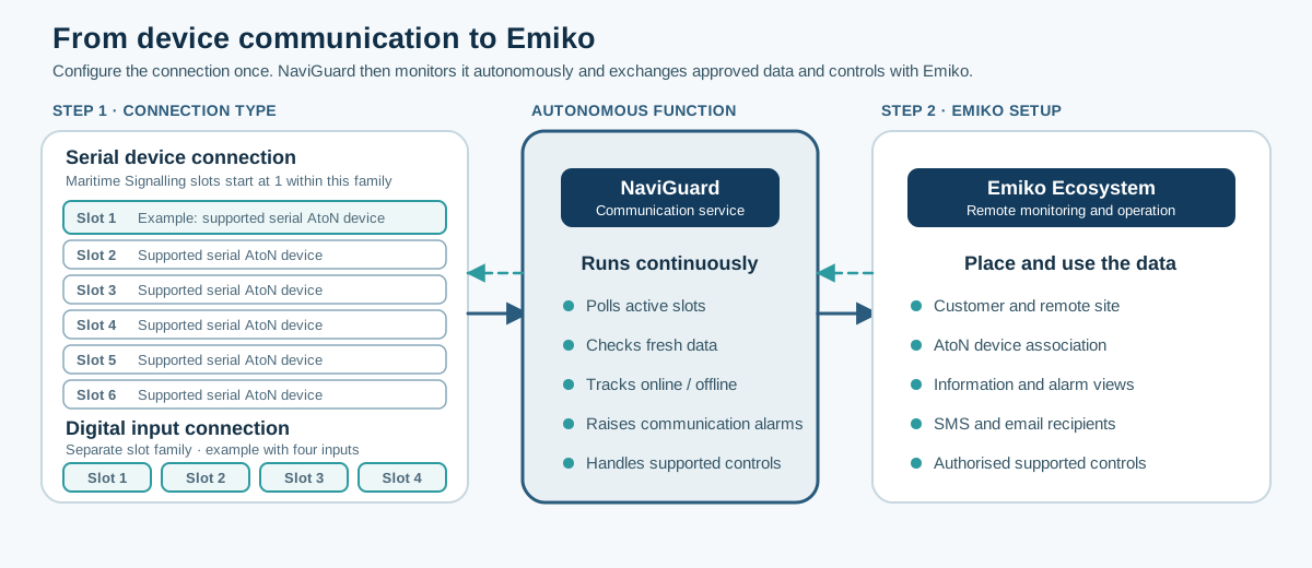
Serial connections and digital inputs use separate slot families, each starting at slot 1. After configuration, NaviGuard monitors the connected instrument and makes its data and alarms available in Emiko.
Before You Start
Complete the physical installation before starting configuration. The NaviGuard controller and the connected AtoN instrument must be powered and ready for operation.
A self-contained solar instrument must have its own working solar and battery supply. An externally powered instrument must be connected to its specified power supply.
Prepare the selected connection type:
Serial instrument connection
Connect the AtoN instrument to the controller through its supported bus, such as RS485 Modbus. Have the manufacturer, model, address, and communication information available.
Digital input connection
Install PowerMonitor for the powered instrument and connect its output to the assigned digital input on the controller. PowerMonitor does not require serial communication with the monitored lantern.
Do This
Recommended configuration flow
- Check the installation.
At the remote site, confirm that the controller, AtoN instrument, power supply, and selected physical connection are installed and ready. - Choose the connection type.
In NaviGuard Configuration, set Connection type to Serial instrument connection for a supported bus connection, or Digital input connection for a PowerMonitor output wired to the controller. - Configure a serial instrument connection.
If serial communication is used, open Communication. Select the manufacturer and model, enter the required bus values, and run the communication test. - Configure a PowerMonitor connection.
If PowerMonitor is used, select the assigned Digital input slot in NaviGuard Configuration. Verify that its live input state changes when PowerMonitor detects the monitored current activity. Do not configure serial communication. - Complete Emiko Setup.
For either connection type, open Emiko Setup. Associate the installation with the correct customer, site, and AtoN instrument, then select the available information, alarms, and supported functions. - Review supported instrument settings.
Open Settings and review only the controls supported by the confirmed model. - Save and verify.
In NaviGuard Configuration, save the setup and reopen it to confirm the stored values. Check that current data from the correct AtoN instrument is visible in Emiko before handover.
Configuration pages
| Page | Use it to |
| Communication | Configure and test the serial instrument connection. Skip this page for a PowerMonitor digital input connection. |
| Emiko Setup | Connect NaviGuard with Emiko Ecosystem for either connection type. |
| Settings | Configure the controls available for the confirmed instrument model. |
| Supported Settings | Compare the information and controls supported by each documented instrument model. |
Available Settings
- The available values and settings depend on the selected instrument type, model, and connection type.
- PowerMonitor shows current activity from the connected instrument. It does not provide the instrument's internal values or settings.
Verify
- Confirm that the saved instrument identity, connection type, and Emiko setup are read back correctly.
- For a serial instrument connection, confirm that live data matches the installed instrument. For PowerMonitor sensing, confirm that current activity from the connected instrument is detected correctly.
- Confirm that the expected current data is visible in Emiko.
If It Fails
Keep the configuration open and use the displayed validation result to identify the failed field or test. Then check:
- Power to the controller and connected instrument, when external power is required.
- The physical serial or digital input connection.
- The selected connection type, slot, and instrument identity.
- The serial communication values, when a serial instrument connection is used.
- Whether current live data is received from the expected instrument or PowerMonitor input.
- The Emiko setup and whether the expected data is visible in Emiko.
Controls remain unavailable when they are not supported by the selected instrument model.
Next Step
Continue according to the selected connection type, then complete Emiko setup for every installation.